- UART stands for Universal Asynchronous Receiver Transmitter.
- It is a way to transmit data from one device to another.
- The 9 pin serial port that are still standard on most computers is an example of a UART.
- The baud rate is the number of bits that can be sent in one second. This is NOT the same as the amount of data that can be sent
- The data rate is always less than the maximum transmission rate.
- Most of the time, you need to send 11 bits to be able to receiver one byte of data.
- The parity bit is a bit used to check the integrity of the data. Usually it counts the number of ones (or zeros it’s the same thing), and indicates whether the number is even or odd. This ensures that if there is an error in ONE bit, the receiver will be able to detect it.
- Overall, the system works like this (one way transmission): A wire connects from the transmission output pin of the transmitter to the reception input pin of the receiver.
- Once the wires are established and the baud rate is determined on BOTH parties, the transmission can begin.

- Each section of the grid represents one time unit equal to the inverse of the baud rate. For example, if we were at 2400 bps, then each section of the grid in the above picture represents 1sec/2400 = 416.7 usec.
- When a transmission begins, the transmitter must first pull the line down to a zero, for one baud period. Then it sends the data, with the least significant bit (lsb) of the byte first. Next the transmitter sends the parity, and lastly, pulls the line back to a high, the stop bit, to indicate that the transmission has ended. Another transmission cannot begin until at least the end of the stop bit. (There can be one or more start/stop bits).

I2C Protocol
- Most electronics today uses I2c to reduce design cost and pin count, uses the I2C bus for inter-IC.
- I2C is a communications bus invented by Philips.Ø
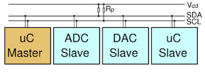
- The I2C bus requires two wires to be connected between the master and slaves, as well as a return (GND) wire.
- There are provisions in the I2C standard for multi-master environments, as well as 10 bit addressing.
- The most simple and commonly used configuration is the single master, 7 bit addressing.
- I2C is synchronous form of communication.
- The master device sends both the data signal, as well as the clock signal, with the exception during data reads. The receiver syncs up with the clock signal, and samples the data on the rising edge of the clock. Ultimately, this means that the transmitter and receiver do not need to know the clock rate because a clock signal is sent along with data.
- In I2C more than 1 receiver (slave) can be selected. This is the advantage over UART.
- The convention is to name the data line SDA, and the clock line SCL.
- Hardware:
- Obviously, you’ll need to have two devices: a master I2C device and a slave I2C device.
- Second, the I2C bus is an open drain pull-down bus. What this means is that the bus needs to be pulled up to a nominal voltage (Vdd) when no devices are occupying the wires. This assures that when the bus is idle, the voltages on data and clock are always at Vdd.
- Usually 3.3 to -2v or +5 to -5 V.
- Communications:

- Let’s say there is one master device and one slave device on an I2C bus line with pull-up resistors pulling to 3.3V.
- When the bus is idle, both the SCL and SDA lines are pulled high by the pull-up resistors.
- If the master wants to send a byte of data, it must first initiate a start bit (Label S), where the SDA line is pulled to a logical 0, while maintaining a logical 1 on the SCL line.
- Next it starts sending a clock signal. Because the SCL is pulled high at the start bit, the master must pull SCL down for half a clock cycle, before the first rising edge.
- Data is only sampled on the rising edge, at all other times, the master is allowed to transition the SDA between a logical 0 and a logical 1.
- On the first rising edge, the SDA line must have stabilized.
- The slave device samples the data (Label B1). This process is repeated until the 8th rising edge, or the 8th bit.(7bits for address and 1 bit specifies read(1)/write(0))
- Right after the 8th rising edge, the master device releases control of the SDA line. It has finished sending its data, and is now awaiting a response from the slave device.
- The slave device has one clock cycle to transition the SDA clock to a logical 0 to acknowledge the reception of the data byte. (/ACK bit)(if ack is 0 slave says data received properly, if 1 ,something went wrong).
- The master then sends a 9th rising edge on the SCL line, and samples the SDA line.
- Lastly the SCL is held high, and subsequently the SDA line is pulled high to signal a stop bit (P).
- I2C Packet

- 3bytes are send 8bits-device address, wordaddress-8bits, data- 8bits
- The first 7 bits is the slave device address. In order for the I2C bus to allow for multiple slaves, the master must indicate which device the message is intended.
- Obviously there cannot be multiple slaves with the same address. This would create a collision on the I2C bus.
- The 8th bit of the first byte is the read/write indicator.
- If the bit is a 0, the master wants to write a byte, if it is a 1, the master intends to read.
- Next, on the 9th bit of the first byte, the master waits for an acknowledge bit from the slave.
- If the /ACK is a 1, a non-acknowledge, then the master thinks there is no slave with the sent address. It terminates the packet with a STOP bit. However, if a slave does send back a /ACK with logical 0, then the master device begins sending the second byte.
- Whenever I want to write to the device, I must specify which one of the 256 memory locations I wish to write to. This is what the second byte of the packet is usually used for.
- On the 9th byte of the second byte the slave device must acknowledge that the specified address exists as one of the slave device’s internal addresses.
- Lastly, the master device sends the data it intends to write. This is usually referred to as the data byte.
- Finally the slave device acknowledges the received byte, and the communications is terminated by a stop bit.
- Other pattern packet
-

- I²C is limited to 1Mbps in Fast Mode+ and to 3.4 Mbps in High Speed Mode.


SPI Protocol
- This protocol is basically limited to 127 devices, and a memory device address space of 256 bytes.
- In SPI, there is no set order on how the data is accessed.
- I can set up the data access in any which way I want.
- I can have the memory address width to be 8 or 16 bits for example, and set the data width to be 8 or 16 or even 32 bits.
- There is one big advantages going for the SPI protocol compared to I2c is that it is fast. Any times you have a large amount of access, for example storing/retrieving a large table
- The protocol usually allows up to 10Mb/s whereas the I2C usually tapers out at around 400Kb/s.
- Physical Connections
-

- 3 common signals + 1 device specific (CS).
- SCLK is the serial clock given by the micro controller. It is used by the slave devices to sample the incoming data and output the outgoing data.
- There are two data lines going to and from the microcontroller.(MOSI –MISO)or (SDO-SDI).
- Unlike I2C, which selects the device according to the chip address in the first byte of a data packet, device selection in SPI is accomplished by the CSB/SS signal. )“chip select bar” (CSB) or “slave select” (SS)).i.e. (/CS – The signal is active low)
- When the signal for a particular device is lowered, that device is selected and considered active.
- Timing
-

- When configuring your microcontroller, there are usually two settings that you need to take into account: clock polarity and clock phase.
- 1. CPHA = 0, CPOL = 0 – first bit starts as soon as SS is lowered, data sampled at rising edge of clock, data changes on falling edge.

- 2. CPHA = 0, CPOL = 1 –first bit starts as soon as SS is lowered, data sampled at falling edge, data changes on rising edge.

- 3. CPHA = 1, CPOL = 0 – first bit starts on first clock edge, data sampled at rising edge, data changes on falling edge.(No wfmS)
- 4. CPHA = 1, CPOL = 1 – first bit starts on first clock edge, data sampled at falling edge, data changes on rising edge. .(No wfmS)
-

- I can see that the first bit is already active even before the first clock edge. Also the data changes on the falling edge and is sampled at the rising edge.
- SPI is full duplex

- Half duplex Full Duplex
- SPEED 10MBPS


- SD/MMC (Secure Digital/Multimedia Card) cards are small, high-speed storage media for portable items such as digital cameras, mobile phones, net book computers and similar devices.
- The communications protocol is similar to SPI protocol.
- SD was developed out of the MMC format.
- Signals used are CLK, Data and CMD.
- Modes – SDR-DDR-BOOT
- Concepts:
- CLK: Each cycle of this signal directs a one bit transfer on the command and either a one bit (1x) (SDR)or a two bits transfer (2x) (DDR)on all the data lines.
-

- One Bit transfer on CMD line fig1
-

- One Bit transfer on DATA line (SDR) fig2 (only rising edge)

- Two Bit transfer on DATA line (DDR) fig3 (rising edge and falling edge)
- CMD: This signal is a bidirectional command channel used for card initialization and transfer of commands.
- Commands are sent from the Multimedia Card bus master to the card and responses are sent from the card to the host.
- DAT0-DAT7(Data Lines): These are bidirectional data channels. Only the card or the host is driving these signals at a time.
- Packet Format


- Total of 48 bits
- A command always starts with a start bit (always ‘0’), followed by the bit indicating the direction of transmission (host = ‘1’).(card =0)
- The next 6 bits indicate the index of the command, this value being interpreted as a binary coded number (between 0 and 63).
- Some commands need an argument (e.g. an address), which is coded by 32 bits.
- All commands are protected by a CRC (7 bits).
- 1 end bit.
- Based on command index we can get to know the state of host or receiver.
- Based on transmission bit we will get to know who is communicating.
- Data starts sampled at the rising edge of the clock.


CAN Protocol
- The CAN communication protocol is a CSMA/CD protocol. Carrier Sense Multiple Access with Collision Detection.
- What this means is that every node on the network must monitor the bus for a period of no activity before trying to send a message on the bus (Carrier Sense).
- Also, once this period of no activity occurs, every node on the bus has an equal opportunity to transmit a message (Multiple Access).
- If two nodes on the network start transmitting at the same time, the nodes will detect the ‘collision’ and take the appropriate action.
- First, logic states need to be defined as dominant (0) or recessive(1).
- Second, the transmitting node must monitor the state of the bus to see if the logic state it is trying to send actually appears on the bus.
- A dominant bit state will always win arbitration over a recessive bit state, therefore the lower the value in the Message Identifier (the field used in the message arbitration process), the higher the priority of the message.
- CAN protocol is a message-based protocol, not an address based protocol.
- This means that messages are not transmitted from one node to another node based on addresses.
- Embedded in the CAN message itself is the priority and the contents of the data being transmitted.
- All nodes in the system receive every message transmitted on the bus (and will acknowledge if the message was properly received).
- It is up to each node in the system to decide whether the message received should be immediately discarded or kept to be processed.
- For example, an automotive airbag sensor can be connected via CAN to a safety system router node only. This router node takes in other safety system information and routes it to all other nodes on the safety system network. Then all the other nodes on the safety system network can receive the latest airbag sensor information from the router at the same time, acknowledge if the message was received properly, and decide whether to utilize this information or discard it.
- Another useful feature built into the CAN protocol is the ability for a node to request information from other nodes. This is called a Remote Transmit Request (RTR).
- For example, a safety system in a car gets frequent updates from critical sensors like the airbags, but it may not receive frequent updates from other sensors like the oil pressure sensor or the low battery sensor to make sure they are functioning properly. Periodically, the safety system can request data from these other sensors and perform a thorough safety system check. The system designer can utilize this feature to minimize network traffic while still maintaining the integrity of the network.
- One additional benefit of this message-based protocol is that additional nodes can be added to the system without the necessity to reprogram all other nodes to recognize this addition. This new node will start receiving messages from the network and, based on the message ID, decide whether to process or discard the received information.
- FRAME DESCRIPTION
- CAN protocol define four different types of messages (or Frames).
- 1. DATA FRAME.
- 2. Remote Frame, Frame, which is basically a Data Frame with the RTR bit set to signify it is a Remote Transmit Request.
- 3. Error Frame – handling errors - Error Frames are generated by nodes that detect any one of the many protocol errors defined by CAN.
- 4. Overload Frame –handling errors are generated by nodes that require more time to process messages already received
- DATA FRAME(44 +8N)
- 1. Arbitration Field 12bits (11 identifier bits and 1 RTR bit)
- 2. Control Fields 6 bits
- 3. Data Fields no of data bytes described in the data length code of control field.
- 4. CRC Fields 15 bits + 1 crc delimeter
- 5. 2-bit Acknowledge Field and an End of Frame(7bits)).
FlexRay Protocol (Image Courtesy - NI )
- For automobiles to continue to improve safety, increase performance, reduce environmental impact, and enhance comfort, the speed, quantity and reliability of data communicated between a car's electronic controls units (ECU) must increase.


- FlexRay uses unshielded twisted pair cabling to connect nodes together
- FlexRay Topology

- Protocol
- The FlexRay protocol is a unique time-triggered protocol.
- FlexRay manages multiple nodes with a Time Division Multiple Access or TDMA scheme.( two nodes were to write at the same time).
- Every FlexRay node is synchronized to the same clock, and each nodes waits for its turn to write on the bus.
- Communication Cycle

- Static Segment
Reserved slots for deterministic data that arrives at a fixed period. 
- The segment is broken up into slots, each slot containing a reserved frame of data. When each slot occurs in time, the reserved ECU has the opportunity to transmit its data into that slot. Once that time passes, the ECU must wait until the next cycle to transmit its data in that slot.
- If an ECU goes offline or decides not to transmit data, its slot remains open and is not used by any other ECU, as shown in Figure 4.
- Dynamic Segment
The dynamic segment behaves in a fashion similar to CAN and is used for a wider variety of event-based data that does not require determinism. 

- Symbol Window
Typically used for network maintenance and signaling for starting the network. - Network Idle Time
A known "quiet" time used to maintain synchronization between node clocks. The ECUs make use of this idle time to make adjustments for any drift that may have occurred during the previous cycle. - FRAME FORMAT

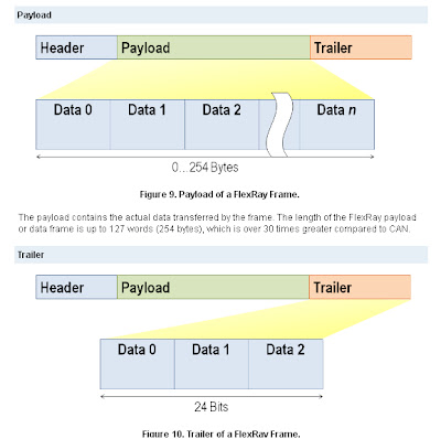
- The Header is 5 bytes (40 bits) long and includes the following fields:
- Status Bits - 5 bits
- Frame ID - 11 bits
- Payload Length - 7 bits
- Header CRC - 11 bits
- Cycle Count - 6 bits
- The Frame ID defines the slot in which the frame should be transmitted and is used for prioritizing event-triggered frames.
- The Payload Length contains the number of words which are transferred in the frame.
- The Header CRC is used to detect errors during the transfer.


No comments:
Post a Comment